Isometric Tile Map
Isometric Tile Map
A quick note, this is sort of written with the intent that one day the engine may be released. Hopefully that comes to fruition, but for now it’s just for reference.The Dusk Tactics Engine (DTE) uses a non-staggered 2D isometric tile map. We’ll assume you know what a tile map is (a map made of tiles) and jump right in.
Isometric Tile
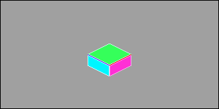
There’s a few different ways you can go about making an isometric tile. You can use basic squares and render them in real-time by rotating by 45° and shrinking the Y axis by half. I decided to go with a ‘building block’ model and create a pre-rendered isometric tile as a base tile. First we have our tile. This is the atom of our world. The decision was to go with a 64 x 32 top, with a depth of 16. The tile ‘walls’ are the blue and pink portions on either side while the top green portion is our ‘floor’. The dark blue line above the left wall, and the darker red line above the pink wall show us the outer boundaries of our top ‘floor’ tile. These two lines are a part of the larger green tile and measure to 64 x 32.
The image above is magnified to make it easier to see, the actual size is closer to the next image.
 We start to get more into art when we talk about why they are there, but for now just know they are for making edge tiles. These lines are covered when multiple tiles are stacked, so they only show when the tile is on top of the column.
As I mentioned above, maps are essentially 2D arrays of columns, with columns being a 1D vertical array of stacked tiles. The maps are created similar to Legos or Minecraft where tiles are layered into columns across the X,Y axis.
The main reason for this setup is to preserve something we call z-depth draw order. Since we only have 2 dimensions to work with, we need to use tricks to make it look like a map has depth. This allows units to walk behind or in front of different tiles depending on their location, essentially the scene renders correctly.
Isometric Tile Map
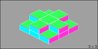
 With a single tile as a building block, using the method above you can create nearly any type of map you want, like the 3 x 3 map to the left.
The only prohibitions with this method, which technically could be worked around, are things like being able to walk under a bridge.
Basically you can’t have 2 units in a single column.
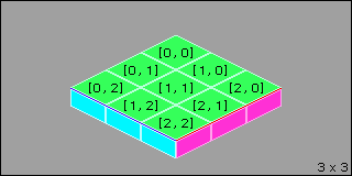
 The coordinate system, [X,Y] starts at the back-most row. This is [0,0]. The X axis increases from left to right while the Y axis increases from back to front. Since you’re working with indexes, the largest value will always be n-1 since we start at 0.
You can also represent the tile coordinates in 3 dimensions using the layer for our faux Z value. In this instance, the tiles in the picture to the left would be [0,0,0] through [2,2,0].
 As we build upward one thing you’ll notice is how the tiles overlap. The blue/red edge lines I mentioned above are hidden when a tile is stacked on it.
I’ve been using the Tiled Map Editor since it came out, so I stuck with it. To make a proper isometric map in it, I simply create layers and offset them vertically by (layer * -16). This helps to view the map as you edit it, when you load it into the engine, you’ll be loading it column by column so the Tiled format doesn’t matter as much.
Lastly, for pathfinding we use the top tile in each column as that is the only tile units will interact with. The top tiles in the image to the left would be at coordinates [0,1,1], [1,0,1], [1,1,1] (middle), [1,2,1], [2,1,1].

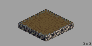
Once we start mixing in different tile types, the map starts to come together as seen above. It’s important to note that if you’re not going for a grid design, isometric tiles in this manner need to have textures that tile correctly for both horizontal and vertical directions. The top ‘floor’ and the side ‘walls’ should tile together as well.
